
弧闪 Calculation Example (IEEE 1584-2018): Why the Smaller Arc Current Can Give the Bigger Hazard
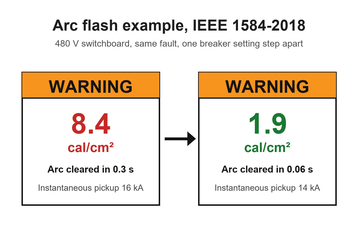
In short: On a 480 V switchboard, the full arcing current (19.3 kA) trips the main breaker instantaneously and gives 1.9 cal/cm². The reduced arcing current that IEEE 1584-2018 also requires (16.9 kA) falls inside the tolerance band of the instantaneous pickup, waits for the 0.3 s short-time delay, and gives 8.4 cal/cm². Lowering the instantaneous pickup by one step brings the result back to 1.9 cal/cm².
An arc flash study is often seen as a simple chain: find the fault current, find how fast the breaker opens, calculate the incident energy. IEEE 1584-2018 adds one step that is easy to overlook, and it can change the answer completely. This article walks through a 480 V example where the smaller of the two arcing currents gives an incident energy more than four times higher than the larger one.
The two arcing currents in IEEE 1584-2018
An arc does 不是 draw the full bolted fault current. IEEE 1584-2018 first calculates the expected arcing current, Iarc, from the bolted fault current, the system voltage, the electrode gap and the electrode configuration.
Because a real arc is unstable, the standard then asks for a second calculation with a reduced arcing current, Iarc_min. The reduction depends on the voltage and the electrode configuration (the arcing current variation correction factor). For each of the two currents you find the protective device's clearing time and calculate the incident energy. The higher of the two results is the one you report.
The reason is the protective device. A lower current can move a breaker or fuse into a slower part of its time-current curve. When that happens, the longer arc duration outweighs the lower current.
The example system
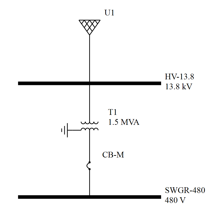
A 480 V switchboard is fed from a 1500 kVA, 13.8/0.48 kV transformer (6.5% impedance) through a 2000 A main power circuit breaker with an electronic trip unit. The utility source is 500 MVA. We want the arc flash result for work on the switchboard bus, which the main breaker clears.
| Input | Value |
|---|---|
| System voltage | 480 V |
| Bolted fault current at the bus, Ibf | 26.5 kA |
| Electrode configuration | VCB (vertical conductors in a box) |
| Gap between conductors | 32 mm |
| Enclosure (W × H × D) | 508 × 508 × 508 mm (20 in) |
| Working distance | 610 mm (24 in) |
| Instantaneous pickup | 8 × 2000 A = 16 kA, tolerance ±10% |
| Clearing time in the instantaneous region | 0.06 s |
| Short-time pickup and delay | 4 × 2000 A = 8 kA, 0.3 s |
The enclosure, gap and working distance are the typical values IEEE 1584-2018 gives for low-voltage switchgear, so no enclosure size correction applies here.
Step 1: the arcing currents
With the IEEE 1584-2018 equations for 480 V and the VCB configuration:
- Arcing current: Iarc = 19.3 kA
- Arcing current variation factor at 480 V: VarCf = 0.247
- Reduced arcing current: Iarc_min = Iarc × (1 − 0.5 × VarCf) = 16.9 kA
Step 2: the clearing time for each current
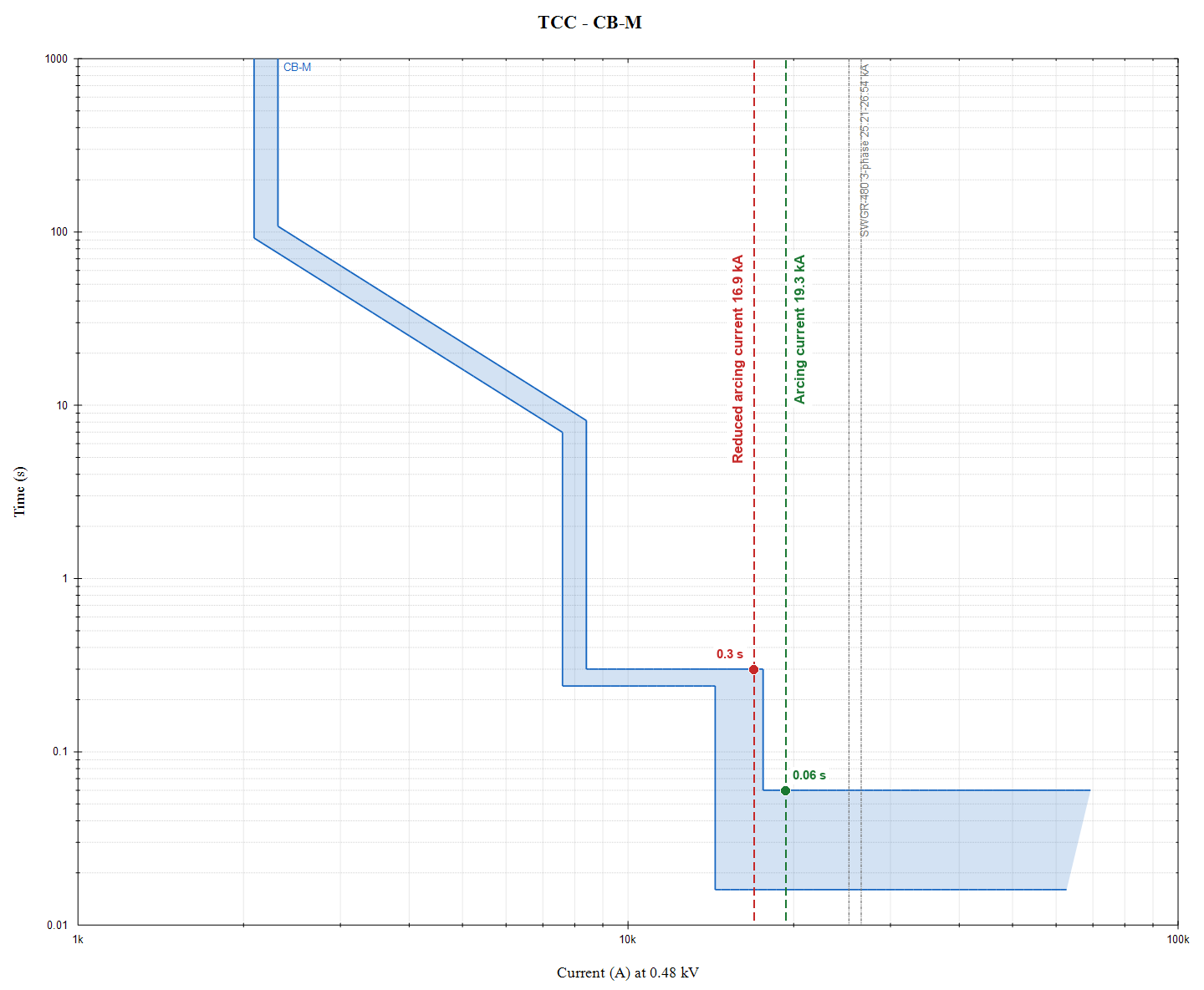
The instantaneous pickup is set at 16 kA. The trip unit in this example has a published pickup tolerance of ±10%, so the breaker is only guaranteed to trip instantaneously above 17.6 kA. This study uses the upper end of the band, which is the conservative choice. Other breakers have other tolerances and clearing times; take them from the manufacturer's curves.
- At 19.3 kA, the current is above 17.6 kA. The breaker trips instantaneously and clears in 0.06 s.
- At 16.9 kA, the current is inside the tolerance band. The breaker may 不是 trip instantaneously, so this study takes the short-time delay: 0.3 s.
A 2.4 kA difference in current has made the arc last five times longer.
Step 3: incident energy and arc flash boundary
| Case | Arcing current | Clearing time | Incident energy at 610 mm | 弧闪 boundary |
|---|---|---|---|---|
| Full arcing current | 19.3 kA | 0.06 s | 1.9 cal/cm² | 812 mm (32 in) |
| Reduced arcing current | 16.9 kA | 0.3 s | 8.4 cal/cm² | 2.05 m (81 in) |
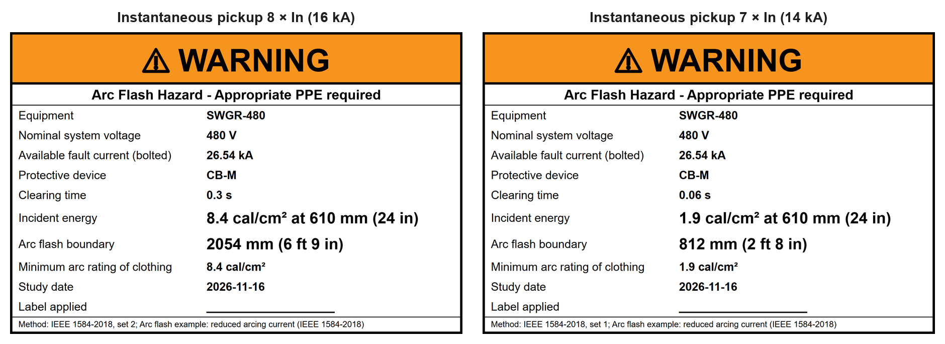
The study result is the higher of the two: 8.4 cal/cm² with an arc flash boundary of 2.05 m. Had the reduced-current case been skipped, the label would have shown 1.9 cal/cm² and a 0.81 m boundary, less than a quarter of the governing calculated incident energy.
How to bring the energy down
The problem is the instantaneous pickup, 不是 the breaker. If the pickup is lowered so that both arcing currents are safely above the top of its tolerance band, both cases clear in 0.06 s:
| Instantaneous pickup | Guaranteed instantaneous above | Reduced-current clearing time | Study result |
|---|---|---|---|
| 20 kA | 22.0 kA | 0.3 s | 9.5 cal/cm², boundary 2.22 m |
| 16 kA (example) | 17.6 kA | 0.3 s | 8.4 cal/cm², boundary 2.05 m |
| 14 kA (lowered) | 15.4 kA | 0.06 s | 1.9 cal/cm², boundary 0.81 m |
The first row shows how much the tolerance matters: at a 20 kA setting, even the full 19.3 kA arcing current is inside the band, so both cases fall to the short-time delay.
Before lowering a setting, check selectivity. A lower instantaneous pickup on the main breaker can reduce coordination with the feeder breakers below it. If full selectivity must be kept, a maintenance mode switch (an energy-reducing setting that is turned on only while people work on the equipment) gives the same result for the duration of the work.
One more caution: an arc on the line side of the main breaker, at its incoming terminals, is 不是 cleared by the main breaker at all. It is cleared by the protective device on the transformer primary, which is usually much slower. That location needs its own result.
The general lesson
For every bus in an arc flash study:
- calculate both the full and the reduced arcing current,
- read the clearing time for each one from the actual device curves and settings, including pickup tolerances,
- report the higher incident energy and the larger arc flash boundary,
- and pay special attention when an arcing current lies close to a pickup setting, because that is where small changes give large jumps in energy.
Doing this by hand for one bus is manageable. Doing it for every bus in a facility, with every device's curve and every contribution, is where errors creep in.
How eeSimu handles this
The example above was built and run in eeSimu. The eeSimu 弧闪 study follows IEEE 1584-2018 for every bus in the one-line model:
- It calculates both the full and the reduced arcing current, and reports the governing case.
- It reads clearing times from the protective devices already in the model, the same breakers, fuses and relays used for protection coordination, and uses the slow edge of each device's tolerance band, as in this example.
- It reports incident energy and arc flash boundary for each bus and prints arc flash labels.
- Its IEEE 1584 calculation is checked against the worked examples in Annex D of the standard.
Because the same model is used for short circuit, protection coordination and arc flash, a change to a trip setting shows up immediately in all three studies, which makes the kind of what-if comparison in this article a matter of minutes.
下载 the example project · Try eeSimu free for 14 days >>
This example is for illustration. 弧闪 studies for real equipment must use the actual system data, device settings and manufacturer information, and be reviewed by a qualified engineer. Results were calculated with eeSimu (IEEE 1584-2018) and checked with an independent calculation.